Hi readers as the motto of the ehobby says learn and share the embedded knowledge. This article tries to focus on fixed point arithmetic. Reason which made me to write this article is a small doubt that troubled me, how to perform fractional arithmetic operation in assembly language?
Fundamentals :
In general for our counting purpose we use natural numbers. Natural numbers are 1,2,3.. so on. Other than this we also come across different variety of numbers in our day to day life. Few examples are. Onion price in India per kilo is Rs 20.50. Distance from Racecourse Road to Jayanagar is 5.75Km. Current consumption by the LED is 20.5mA etc.
If we observe the numbers 20.50, 5.75 and 20.5 these are also numbers but with "radix point". Radix point aka decimal point is the one which separates the integer part and the fractional part in a mixed number. These numbers are rational numbers basically. Rational numbers are those which can be represented in the form of p/q where in p is an integer and q is a non-zero integer. There are two arithmetic ways to do operations on these numbers in computer world.
1) Floating point arithmetic: The basic representation of floating point arithmetic is Significant_Digits x Base E
By seeing the representation itself it is easy to understand that handling the floating point arithmetic is complex process. It increases both time complexity and space complexity of a program. It has an advantage also that increase range as the radix can float to any position in the number.
2) Fixed point As the name indicates in fixed point arithmetic the radix point will be fixed to one position that is two decimal point four decimal point etc. Example for two decimal point arithmetic is as below
12.50 + 13.71 = 26.21
Now consider 26.21. It can be represented as 2621/100.And it can be represented as 2621= 2x10. Taking the discussion further we can also reach out to same result by following way i.e multiply the two operands by 100. so 1250+1371 = 2621. Now we can divide by 100 to get the same result. This is called as scaling. Based on the above discussions we can derive a formula.
Ni = Nm/100 => Nm = Ni/100. Here Nm – Mixed number, Ni – Integer number. This simple formula can be used to scale.
The above formula is for decimal number with two digit fixed arithmetic.
Enter the binary world.
A processor may be using 8 bit, 16 bit and 32 bit operations based on its architecture. For simplicity let us consider the 16 processor.
b15 | b14 | b13 | b12 | b11 | b10 | b9 | b8. | b7 | b6 | b5 | b4 | b3 | b2 | b1 | b0 |
In the above representation bits from b0 to b7 represent the fractional part of the mixed number. For easy identification it is marked in olive green colour. So we have 8 bits to represent the integer part and another eight bit to represent the fractional part. Now let us consider the formula that we have devised i.e. Ni = Nm/100. Now as we are using binary operation that is also by considering the 8 bit fractional part, this formula gets converted to Ni=Nm/256. Where Ni is the unsigned integer representation. Nm is the mixed number. In simple words to convert the mixed numbers to an integer representation in scaling technique simply multiply by 256. (Required the intention is to support 8bit fractional part)
Now let us consider two numbers 1 ¾ and 1 ¼ .
7/4 x 256 = 448 in decimal => 0x1C0 in Hex. and 5/4 x256 = 320 in decimal system => 0x140 in Hex.
So 1 ¾ + 1 ¼ => Scaled version of (0x1C0 + 0x140) => Scaled version of (0x300) => 0x300 => 768/256 =3.00 it is exactly correct ! Hurray J
Here we scaled it using 256 as it is addition. If It is multiplication we need to scale it 256x256. If it is division we need multiply the answer by 256.
Realisation in assembly :-
Please find the code snippet which is used to add the two numbers. It is written in MAXQ assembly language.
ADD:
move AP,#00 //Select Accumulator
move A[0],#0x01C0 // scaled version of 7/4
move A[1],#0x0140 //Scaled version of 5/4
add A[1] //Total sum
sra4 //divide by 16
sra4 //divide by 16 total 16x16 256
move @DP[0],A[0] //store the answer Data memory
ret
For more details related to instruction set please refer to http://www.maxim-ic.com .This code is tested using IAR IDE. We can use the similar logic for multiplication, subtraction and division. Need to change the post scaling factor that's all.
Let me come up with a real embedded application of this implementation some time in future. If you have any queries or feedbacks please contact at ehobby_contact@fastmail.fm
-eguru


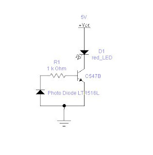
 I have used more electronic workbench 5.12 to draw the circuit. Find the tiny board developed on the general purpose board. It works really fine