Some of the important characteristics of infrared waves are
1] They are not part of the visible spectrum
2] IR waves cannot penetrate in side the walls.
3] Inclusion of IR in your product is cheap.
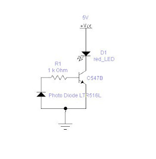
Because of these three reasons we can find IR remotes as standard controlling device. In this article I will show you how to build a simple IR detector circuit. The main aim of the circuit is to blink the LED when the IR signal from a remote falls on it.
Components Required
- 1 Red LED.
- 1 Transistor – BC547B is the one I have used u can use any transistor basically drive a LED.
- 1 Photo diode LTR516
- 5V supply
Design:-
All the remote controls transmit IR of wavelength around 700nm to 800nm. So it is necessary to pick a photo diode which is sensitive to this range. Photo diodes are used in reverse bias condition. They convert incident light in to current. But the current produced by them is insufficient drive a LED. So a transistor is used. Transistor used is the BC547B. It is a small signal amplifier transistor. When the light falls photo diode it generates reverse current which is used switch on the LED.  I have used more electronic workbench 5.12 to draw the circuit. Find the tiny board developed on the general purpose board. It works really fine J
 I have used more electronic workbench 5.12 to draw the circuit. Find the tiny board developed on the general purpose board. It works really fine J
If you have any doubts about this or need any further details please feel free to mail me at contact_ehobby@fastmail.fm
No comments:
Post a Comment