Search The Web

Wednesday, December 28, 2011

Cissembly - where c and assembly meets I

 The world of software development has reached a stage where in merely writing the algorithm generates the code!.There are software which validates other software. But still the demand exists for low level language programing. Lot of firmwares are written using the c and assembly.
  
In my last post i have described how C++ is growing in embedded domain. But in this post i wold like to explain the combination of c and assembly language. Aim is to discuss how exactly we improve the performance by using C for fast development and assembly for fast execution.

Some of the basic thumb rules is to use assembly code to
1) Develop low level drivers which helps to improve the performance. And also helps to enjoy the specialized features the controller.

2) Use assembly code to develop software delays. We can go in the instruction execution cycle details of the data sheet to tune the timing.

3) If you want to decrease the foot print. But for that penalty is increased development time :P

4) Let the application layer in c as it is best idea for portability.

The cocktail of c and assembly language is known as Cissembly.  I love this language as I have coined this word at least!

source code structure may include in line assembly code. c might call a assembly routine or viceversa.
Data handling is a crusial thing because variable or memory access from assembly is out of the purview of the compiler. So if any overlaping occurs in data section then compiler cannot identify it.

To generate a good c and assembly language combination, developer needs to know following things
i) proper understanding of the compiler  especially the topics related to c and assembly
ii) function call conventions.

Please refer my upcoming post "Cissembly - where c and assembly meets II"


For any further information please feal free to mail at contact_ehobby@gmail.com -eguru

Sunday, September 18, 2011

My experiment with C++

 
E Balaguruswamy mentions in his famous book object oriented programming with c++ "C++ is going to replace the C language in near future". It is an important thing to all embedded C developers. So it is better to learn C++ quickly.


A good c programmer can learn C++ in only one week!. This I can guarantee you all because i achieved it with the same amount of time :)


One main thing in OOP is, it helps to design the program based on the real life entities. We can easily extract the real time features to the design using the concepts such as


1) Polymorphism - one name multiple forms

2) Abstractions - Provide only the necessary information

3) Encapsulation- Wrapping up of Data and function together

4)Data hiding- Hide the unnecessary information based to safeguard the data

5)Inheritance- Deriving the features from already existing one


For example if want to write program based on line. Then we need to create point as it is basic necessity.

So line inherits the properties of the point also. So we can make point as base class and line as derived class.


Please find the appended c++ program which will helps to understand inheritance clearly.


/******************************************************************************************************
;All rights reserved -embeddedhobby.blogspot. com
;
;A C++ program written to understand OOP concepts 18-09-2011
;Author: eguru
; Inheritance
;Constructors
;overloading
;******************************************************************************************************/
#include<iostream.h>

class point
{
  int x;                 // x coordinate
  int y;                 // y coordinate
 public:
  point(int x1, int y1)  // parametrized constructor
  {
   x =x1; 
   y =y1;
  }

  point()                // Non parametrised constructor
  {
   x =0;
   y =0;
  }
  void PutData(void);    // function to display the point
};


class line : public point            // line is class which inherits the properties of the derived class.
{
 point point1,point2;             // point is base class
   public:
     void DisplayLength(void);
     line (int x1,int y1,int x2, int y2) : point1(x1, y1), point2(x2, y2) // constructor list
  {
        cout<< " line initialised";
            
  }
  line():point1(), point2()
  {
   cout << " line is initialised zero";
  }

};
/******************************************************************************************************
;All rights reserved -  embeddedhobby.blogspot.com
;******************************************************************************************************/
void line::DisplayLength(void)
{
   point1.PutData();
   point2.PutData();
}
void point::PutData(void)
{
  cout << "\n origin x="<<x;
 cout << "\n origin y= "<<y;
}
main()
{
 cout  << "WellCome to C++";
 cout<<" Input 1 to display line";
 int x;
 cin >>x;
 line straight;
 switch(x)
 {
  case 1:
       cout<< " Line coordinates are as follows" ;
       straight.DisplayLength();
       break;
    
  case 2:
                cout<< " Add code for your experiment" ;
       break;

  default:
    cout << "  Bye Bye ";
       break;
 }
    point ORG;
 cin >>x;
 return 0;
}


For any further information please feel free to mail at contact_ehobby@gmail.com -eguru

Wednesday, July 20, 2011

Computer vs Embedded systems

Hardly we can find any difference between General purpose computer and Embedded systems when we glance over the capabilities. Basically both are computing systems, both have the combination of software and hardware.  But still why there is a separate field called as  "Embedded systems" other than the General purpose computers/ personal computers?
       But if we get in to the detail based on the different integral parts of the system we can list few important differences.
   
No
Characteristics
Embedded System
General Processing Computing System
1
Product quality/performance
Sophisticated
General
2
Presence in a system
Usually it will be  a small part of a large system
Whole system
3
Time constraint 
Output should be available in the specified of time else it may lead to failure
No such strict rule for most of the task
4
Flexibility
Less flexible for modifications as it is developed for specific purpose
More flexible for up gradation 
5
Input/ Output
Nonstandard input output devices.
Standard input output devices
6
System software's used for development 
Generally cross compilers and cross assemblers, RTOS
compilers, assemblers, OS etc
7
Power
Demands low power consumption to sustain in the market
Less restriction. 
8
Packaging of the product
Will be unique and varies from product to product
Most of the time well defined
9
Examples
Washing machine, Cell phone, set top box
Personal computer, Server etc


For any further information please feel free to mail at contact_ehobby@gmail.com -eguru

Friday, April 1, 2011

News from IAR

Please find the latest big news below. A new state machine design and implimentation tool set
 
Click here to view this message in a browser window.
IAR Systems - The Code To Success
 
Welcome to e-News from IAR Systems


This month's industry highlight—Embedded World—was a great success. Thank you to all customers who visited us. We hope to see you at the next big eventEmbedded Systems Conference.

The Power Debugging theme continues, here you'll find the third article in the series. Even more power debug material is to come. Enjoy!

Best regards,
Marie Gylldorff
Corporate Marketing Manager
IAR Systems


EDN Innovation Awards

IAR Systems is a finalist for EDN Innovation Awards 2010. If you haven't voted yet, now is your last chance. Voting ends March 31.


Power debug toolbox of the month

Got some time to spare? Take a nap!
Most embedded systems spend a lot of time waiting for something to happen. It could for example be waiting for user input, a peripheral unit, or just for some time to pass. While waiting, the microcontroller will consume power as long as the CPU is executing instructions, even if it is doing nothing. Fortunately, modern low power microcontrollers provide a plethora of low power modes in which the application can take refuge while waiting, saving a little bit of energy.

Click to continue...


IAR visualSTATE 6.4
  State machine


March saw the arrival of the latest release of IAR visualSTATE, the advanced state machine design and implementation toolset. Let us take a brief look at what's new in this release:
  • A new XML-based file format for the design information
  • Addition of IAR Information Center
  • Addition of examples, including one that can play CD music on your PC 
  • IAR visualSTATE is now a true Unicode application
This might not seem like much to brag about, but let us examine each feature in a bit more detail.
 
March 2011
 
Product News


Want to try the latest edition of a product? Evaluation editions of all new software products are available from www.iar.com/downloads

IAR Embedded Workbench for MAXQ
Version 2.30 includes new optimizations and improved hardware debug support.
Click to continue...

IAR visualSTATE (see also article)
Version 6.4 adds IAR Information center and support for diff and merge.
Click to continue...

IAR Embedded Workbench for CR16C
Version 3.10 adds IAR Information center, C99 compliance, debugger improvements and support for new devices.
 
Events


ESC Silicon Valley 2011

ESC brings together the largest community of designers, technologists, business leaders, and suppliers, all in one place. May 2-5, IAR Systems will be at ESC in San José, California, and we will be hosting several seminars. For more information, and to register for our sessions, go to www.iar.com/escsv2011

TI TechDay
Join Texas Instruments for a day packed with technical design seminars, May 3 in San José, California.
Detailed information and registration

Embedded Systems Expo—ESEC

May 11-13, IAR Systems will participate at ESEC in Tokyo, Japan.


Copyright © 2011 IAR Systems AB
P.O. Box 23051 SE-750 23 Uppsala, Sweden
If you do not wish to receive future newsletters or invitations from us, click here

www.iar.com


Monday, March 21, 2011

TI introduces industry's lowest cost Microcontroller Development Kit


This e-mail may be an advertisement or solicitation.
You are receiving this e-mail from UBM India Pvt Ltd on behalf of Texas Instruments.
MSP-EXP30G2 LaunchPad Kit
$4.30 MSP430 LaunchPad Kit for Value Line Devices
•   Complete open source tool for harnessing
     16-bit performance and ultra-low power
•   FREE SHIPPING for a limited time only
Order Now
More info
Texas Instruments
Introducing the industry's lowest cost microcontroller development kit enabling on-board prototyping, debugging and programming

Easily launch designs and do more for less, with the Value Line series of MSP430™ microcontrollers that deliver 16-bit performance and ultra-low power at 8-bit price.
Integrated Flash Emulation Tool
  • Eliminates need for external tool
  • Integrated USB-powered emulator
  • Includes mini USB cable
  • Program and debug any MSP430 Value Line MCU through the Spy Bi-Wire (2-wire JTAG) protocol
  • Value Line MCUs are code compatible across entire MSP430 line for additional scalability
DIP Target Socket Supports up to 20 pins
  • Easily evaluate, program and debug any MSP430 Value Line MCU
  • Unplug programmed MSP430 Value Line device to be dropped into custom board
  • Alternatively, keep MCU plugged into LaunchPad to be used as standalone system with on-board LEDs, switches and breakout pins.
Two MSP430 Value Line MCUs included
Device Flash RAM GPIO WDT BOR USI Comp ADC
MSP430G2211 2 kB 128 B 10 Y Y Y
MSP430G2231 2 kB 128 B 10 Y Y Y 8ch ADC10
Free software tools and complete online resources For more information visit here.

Sign up for the MCU NewsFlash and my.ti news to get the latest information and offers on the MSP430 Value Line LaunchPad, and other TI MCU devices.
SHARE THIS EMAIL   Facebook   Twitter   LinkedIn   Delicious
my.TI Login| Free Sample| Literature| E2E Community| Distributors| Trademarks| Privacy Policy
© 2011 Texas Instruments Incorporated, 12500 TI Blvd, Dallas, TX 75243

About this e-mail:
TechOnlineIndia respects your time and privacy. If you are not interested in receiving future e-mails from TechOnlineIndia, click here to unsubscribe or please click to view our privacy statement.

You are receiving this message under the e-mail address ivivekbhat@yahoo.com because you are on mailing list of TechOnlineIndia, and you must use this address when trying to unsubscribe.

Any questions about your profile or registration/change of e-mail address please write to techonlineindia@ubmindia.com

To know more about this e-mail please replys this message.

UBM India Pvt Ltd is located at Sagartech Plaza A-119 Sakinaka Junction Andheri East Mumbai 400072.


Fw: IAR KickStart Kit for NXP LPC1227

IAR has release its new product please have a look.
 

This message contains information based on an image.
Problems viewing this email? Click here to open this message in a browser window.


© Copyright 2011 IAR Systems AB.
P.O. Box 23051 SE-750 23 Uppsala, Sweden

This message was sent to ivivekbhat@yahoo.com. If you do not wish to receive future email from us, click here.

www.iar.com


Saturday, March 19, 2011

Hands on - SmartDraw

First thing after "requirement engineering" in any embedded software development life cycle is design. In case of software design choosing a proper way and of-course a design  tool  is a preliminary step . To kick off the software development life cycle,  flow chart designing is a common practice  in low end embedded systems. It not only provides an clear cut idea for coding but also helps as an document, for the whole life time of the project.

Main criteria to choose design  tool are.
1]  How fast you can develop the design using the tool
2] Does the design what you make is portable to other document formats like .doc, .ppt etc.
3] Does it provide the required design blocks for your intended design.
4] And most importantly cost!

Let me share my experience with SmartDraw tool. Believe me it is really amazing tool. Using this you can really draw almost all type of diagrams. It is really independent of discipline. Finance, management, all types engineering branches can benefit from the tool. Even we can draw electronic circuit.
t
Trial version can be downloaded from the  link http://www.smartdraw.com/downloads/.
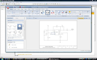
Just test the capabilities of the SmartDraw i made a flow chart. Later i sent it to Microsoft excel. Believe me i am able  create the flow chart within 5 minutes.
Snap of the same you can find below.Its really fantastic tool. It can save  nearly 80% of documentation during design phase of project. Hats of to SmartDraw!

For any further information please feal free to mail at contact_ehobby@fastmail.fm
 -eguru

Friday, March 18, 2011

A help to get a help - PSpice

Recently i got a chance to work with PSpice evaluation version 9.1 from cadense system. I just wanted it to simulate a simple circuit. I could download student version from the link http://www.electronics-lab.com/downlaods/schematic/o13/
What is the thing you after the installation of a tool look for help. I also tried the same thing. But it was not working. If your Net connection is always up then there is n problem you can always get the help through browsing.

After googling for a some time and following link from the error help. I came to know that the problem is due to the fact that the the help format is now where supported by Windows Vista, Windows 7. Solution is again Microsoft itself. From Microsoft download center download the Winhlp32.exe. Install it and enjoy :)

For quries please contact_ehobby@fastmail.fm

eguru

Wednesday, March 16, 2011

IR Indicator

By definition of electromagnetic spectrum an electromagnetic waves characteristic largely depends upon the frequency of the wave. So let us keep this discussion to 1mm 750nm wavelength.

Some of the important characteristics of infrared waves are
1] They are not part of the visible spectrum
2] IR waves cannot penetrate in side the walls.
3] Inclusion of IR in your product is cheap.

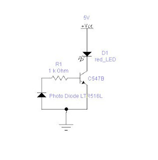
Because of these three reasons we can find IR remotes as standard controlling device. In this article I will show you how to build a simple IR detector circuit. The main aim of the circuit is to blink the LED when the IR signal from a remote falls on it.

Components Required

  1. 1 Red LED.
  2. 1 Transistor – BC547B is the one I have used u can use any transistor basically drive a LED.
  3. 1 Photo diode LTR516
  4. 5V supply

Design:-

All the remote controls transmit IR of wavelength around 700nm to 800nm. So it is necessary to pick a photo diode which is sensitive to this range. Photo diodes are used in reverse bias condition. They convert incident light in to current. But the current produced by them is insufficient drive a LED. So a transistor is used. Transistor used is the BC547B. It is a small signal amplifier transistor. When the light falls photo diode it generates reverse current which is used switch on the LED. I have used more electronic workbench 5.12 to draw the circuit. Find the tiny board developed on the general purpose board. It works really fine J


If you have any doubts about this or need any further details please feel free to mail me at contact_ehobby@fastmail.fm

Monday, March 14, 2011

Fixed Point Arithmetic – in Assembly

Hi readers as the motto of the ehobby says learn and share the embedded knowledge. This article tries to focus on fixed point arithmetic. Reason which made me to write this article is a small doubt that troubled me, how to perform fractional arithmetic operation in assembly language?

Fundamentals :

In general for our counting purpose we use natural numbers. Natural numbers are 1,2,3.. so on. Other than this we also come across different variety of numbers in our day to day life. Few examples are. Onion price in India per kilo is Rs 20.50. Distance from Racecourse Road to Jayanagar is 5.75Km. Current consumption by the LED is 20.5mA etc.

If we observe the numbers 20.50, 5.75 and 20.5 these are also numbers but with "radix point". Radix point aka decimal point is the one which separates the integer part and the fractional part in a mixed number. These numbers are rational numbers basically. Rational numbers are those which can be represented in the form of p/q where in p is an integer and q is a non-zero integer. There are two arithmetic ways to do operations on these numbers in computer world.

1) Floating point arithmetic: The basic representation of floating point arithmetic is Significant_Digits x Base E
By seeing the representation itself it is easy to understand that handling the floating point arithmetic is complex process. It increases both time complexity and space complexity of a program. It has an advantage also that increase range as the radix can float to any position in the number.

2) Fixed point As the name indicates in fixed point arithmetic the radix point will be fixed to one position that is two decimal point four decimal point etc. Example for two decimal point arithmetic is as below

12.50 + 13.71 = 26.21

Now consider 26.21. It can be represented as 2621/100.And it can be represented as 2621= 2x10. Taking the discussion further we can also reach out to same result by following way i.e multiply the two operands by 100. so 1250+1371 = 2621. Now we can divide by 100 to get the same result. This is called as scaling. Based on the above discussions we can derive a formula.

Ni = Nm/100 => Nm = Ni/100. Here Nm – Mixed number, Ni – Integer number. This simple formula can be used to scale.
The above formula is for decimal number with two digit fixed arithmetic.

Enter the binary world.
A processor may be using 8 bit, 16 bit and 32 bit operations based on its architecture. For simplicity let us consider the 16 processor.

b15

b14

b13

b12

b11

b10

b9

b8.

b7

b6

b5

b4

b3

b2

b1

b0

In the above representation bits from b0 to b7 represent the fractional part of the mixed number. For easy identification it is marked in olive green colour. So we have 8 bits to represent the integer part and another eight bit to represent the fractional part. Now let us consider the formula that we have devised i.e. Ni = Nm/100. Now as we are using binary operation that is also by considering the 8 bit fractional part, this formula gets converted to Ni=Nm/256. Where Ni is the unsigned integer representation. Nm is the mixed number. In simple words to convert the mixed numbers to an integer representation in scaling technique simply multiply by 256. (Required the intention is to support 8bit fractional part)
Now let us consider two numbers 1 ¾ and 1 ¼ .
7/4 x 256 = 448 in decimal => 0x1C0 in Hex. and 5/4 x256 = 320 in decimal system => 0x140 in Hex.

So 1 ¾ + 1 ¼ => Scaled version of (0x1C0 + 0x140) => Scaled version of (0x300) => 0x300 => 768/256 =3.00 it is exactly correct ! Hurray J

Here we scaled it using 256 as it is addition. If It is multiplication we need to scale it 256x256. If it is division we need multiply the answer by 256.

Realisation in assembly :-

Please find the code snippet which is used to add the two numbers. It is written in MAXQ assembly language.

ADD:
move AP,#00 //Select Accumulator
move A[0],#0x01C0 // scaled version of 7/4
move A[1],#0x0140 //Scaled version of 5/4
add A[1] //Total sum
sra4 //divide by 16
sra4 //divide by 16 total 16x16 256
move @DP[0],A[0] //store the answer Data memory
ret
For more details related to instruction set please refer to http://www.maxim-ic.com .This code is tested using IAR IDE. We can use the similar logic for multiplication, subtraction and division. Need to change the post scaling factor that's all.

Let me come up with a real embedded application of this implementation some time in future. If you have any queries or feedbacks please contact at ehobby_contact@fastmail.fm

-eguru
Monday, January 3, 2011

objective

This blog is a show case of my electronic hobby adventures. Objective is to help like minded people, enthusiasts and students in one or the other way by sharing my experience.

egurubhat